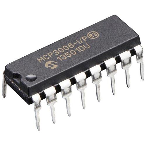
This integrated circuit can be used to read an analog voltage level on a device which only supports digital inputs.
For circuit, pin and interface specification see this datasheet
Usage
The circuit can handle up to 8 different analog inputs and uses an SPI-bus to communicate the voltage levels to other devices (interface described in the datasheet). The voltage is reported as a 10-bit integer (0-1023) which corresponds to the fraction of the read voltage compared to the reference voltage.
Extra information
Within the Appivo platform, all SPI communication is done in bytes. This means that in order to get the circuit working, one will have to check the datasheet for the 8-bit interface and the extra quirks that it entails.
To connect the ADC to a raspberry pi connect the pins as described in the table below
| MCP3008 | CLK | Dout | Din | CS/SHDN |
| Raspberry PI | SCLK | MISO | MOSI | CE0 |
Sample code
The ADC does not continuously provide it’s currently read value, instead it responds to requests on the SPI bus where it is possible to request either just a single pins value or the differential between two pins. On a bus where there is full control over what bits are sent, it is possible to just send 5 bits - a start bit followed by 4 bits that represent single/differential + pin selector (see table 5-2 on page 19 of the datasheet for specification of the 4 selector bits). In the Appivo platform it is only possible to send a complete byte at a time but thankfully the ADC supports this operating mode too. Instead of sending just 5 bits it is necessary to send 3 bytes. The first byte is the start bit with leading zeros 0b00000001, the second byte is the 4 selector bits followed by anything (the ADC doesn’t care what the lower 5 bits are) 0bssssxxxx (s = selector bit, x = don’t care bit), the last byte is just there for timing purposes and the ADC doesn’t care what you send 0bxxxxxxxx (x = don’t care bit). The ADC will respond with 3 bytes where the first byte is just padding 0bxxxxxxxx (x = don’t care), the second byte is the upper 3 bits of the measurement preceded by padding bits and a 0 bit 0bxxxxx0b8b7, the third byte is the lower 8 bits of the measurement 0bb7b6b5b4b3b2b1b0. This means that some bit-masking and bit-shifting is required to re-assemble the 10 bit integer
pseudo code
- send request to the device [0x01, 0xSX, 0xXX] (S = selector, X = don’t care) and store response
- parse the response bytes into a 10-bit unsigned integer
Javascript
//get a reference to the ADC on SPI
var sensor = context.getModule("spi").getDevice(0, 0);

//send the measurement request and store the response
//here the request is for single-ended read of CH0 (0x80 = 0b10000000)
var bytes = sensor.write([0x01, 0x80, 0x00]);

//parse the recieved bytes into a 10 bit unsigned integer by masking out
//the lower 3 bits of byte 2 and shifting them up then simply add byte 3
var uInt10 = ((0x03 & bytes[1]) << 8) + bytes[2];

//the read voltage can be gotten by dividing the ADC response by
//1023 and multiplying it with the reference voltage, in this case 5.0 V
var voltage = (uInt10 / 1023) * 5.0;
